
Gear machining technologies are divided into several methods, in this article we will describe the gear generating method (hobbing and shaping), which is the result of the tool rolling with the workpiece, and in addition, there is a continuous machining cycle, i.e. splitting takes place during the machining of the wheel.
The forming method and other gear machining technologies are described here and here.
The gear generating method
The gear generating method takes place when during the teeth cut, the tool performs the relative movement that would exist if the part had already been cut. In addition to the movement of the main tool, there is also a rolling motion, otherwise known as rolling away, the final effect generating involute tooth profile. The rolling motion consists of the rotary motion of the machined gear and the feed motion:
-
machined gear in the Maag method,
-
machined gear in the Maag method,
-
rotational movement of the hob (tooth arrangement along the helix).
In the gear generating method the workpiece and the tool roll one after another in the following positions [1], shown in Fig. 1:

Fig. 1. Sequential position of the cutting edge in gear generating method [1]
This type of processing allows to obtain optimal conditions for generating an involute profile. Thanks to this, gears with such a profile have high gearing efficiency and a constant direction and size of the transferred forces, resulting in the absence of vibrations [2].
Chiselling using the Maag method - an unused method of machining teeth with a chisel in the form of a toothed bar (rack), performing the main reciprocating movement. The machined wheel performs both rotary and feed motion.

Fig. 2. Chiseling using the Maag method [3]
In Figure 2, it is possible to notice successive phases of the cycle in which the rack performs reciprocating movements, while the machined wheel, apart from the aforementioned rotational movement, also performs a sliding movement [3].
Planning by the Sunderland method - a method like the previous one, except that the feed movement is performed by a rack.

Fig. 3. Chiseling with the Sunderland method [3]
Figure 3 shows the phases of the Sunderland gear generating method, the gear rotates, while the rack makes reciprocating and sliding movements, initially vertically upwards and then vertically downwards.

Fig. 4. Feed in the method: a) Maag with a wheel, b) Sunderland with a bar [3]
Figure 4 shows a comparison of both the aforementioned gear generating machining using Maag and Sunderland methods. The feed movement enabling the production of the involute is realized either by the machined gear or by the tool, in the case of these methods by the chisel in the form of a toothed bar (rack). Both methods used to be used to machine external gears and are practically unused today, due to the much lower achievable machining parameters, and thus also a much longer processing time, they have been replaced by the further described hobbing and shaping.
Shaping with the Fellows method - a method with the use of Fellows shaper cutters (Fig. 5) on a variety of shaping machines called shaping machines. The Fellows shaper cutters performs both rotary and reciprocating motion, the machined gear only performs a rotary motion. The method is mainly used for finishing internal gearing [1]. In shaping roughing is usually avoided to eliminate the grinding process which is problematic due to the way the grinding wheel reaches the grinded gear.

Fig. 5. Different types of Fellows shaper cutters: a) disk, b) boss, c) shaft [1]
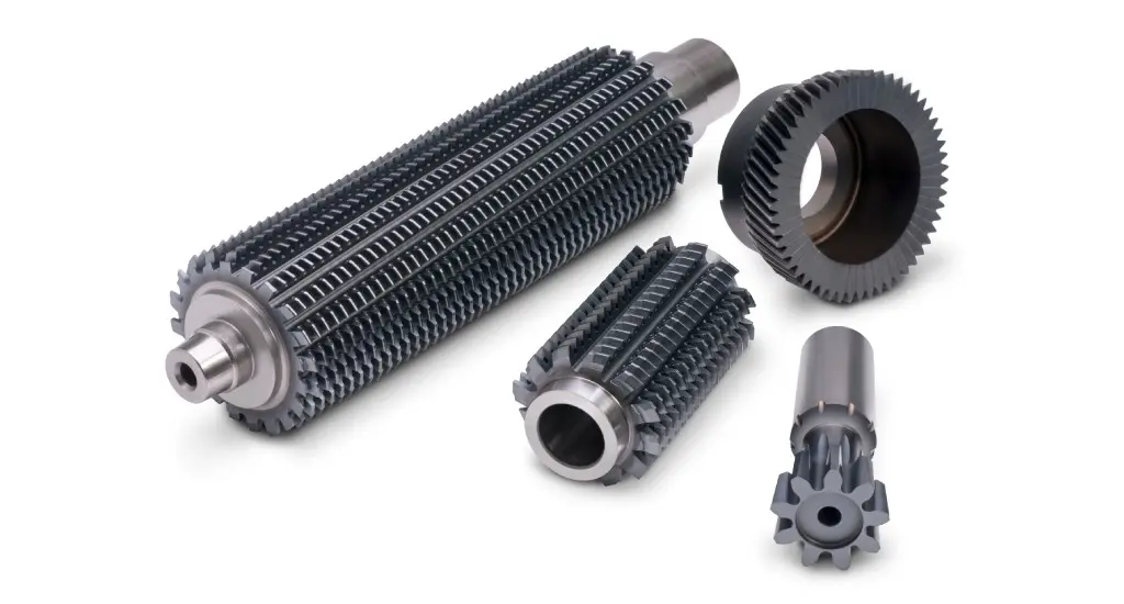
Milling with a hobbing cutter (hob) - a method which works very similar to the connection of a worm wheel with a worm. After a single revolution of the hob, the gear will rotate by an angle corresponding to k-times the scale, depending on the number of turns [3].

Fig. 6. Kinematics of counter-rotating machining of a gear with a hob [3]

Fig. 7. A pictorial representation of the counter-rotating machining of a gear [4]
The hobs performs both rotary and feed movements, and the machined gear only rotates. The arrangement of the teeth of the hob along a helical line imitates the movement of the rack. An example of conventional machining with a hob cutter is shown in Figures 6 and 7.
The greatest advantage of the hobbing method is its versatility and wide range of applications in terms of the number of teeth in the part being processed. Cutting the teeth with the same profile with one gear cutting tool (e.g., a shaping disk cutter) or a Fellows shaper cutter is not possible for teeth with a different number of teeth due to the risk of obtaining an incorrect profile. In the case of machining with a hob, we gain much greater flexibility. It is still likely to achieve a bad profile in an extremely different number of teeth, for example, if the difference is more than 100, but for smaller ranges there is no need to possess a whole range of contouring tools (gear milling cutter sets), one hob is enough. During operation, the tool is mounted on a mandrel at an appropriate, strictly defined angle, with the direction also depending on the direction of the tooth inclination, as shown in Figure 8.

Fig. 8. Direction of setting the hob on the machine depending on the direction of inclination of the teeth in the machined part [3]
Due to the kinematics, hobbing with a hob can be divided, as in the case of classical milling, into two types:
-
climb hobbing,
-
up-cut hobbing.
Both types are shown in Figure 9. It should also be remembered that the direction of rotation of the machined gear is also dependent on the height factor of the tooth head. If the coefficient is negative, the machined wheel should turn clockwise, if positive, it should be counterclockwise.

Fig. 9. Direction of wheel rotation in climb hobbing (right) and up-cut hobbing (left) depending on the tooth head height factor [4]
Climb hobbing is much more often used due to the better distribution of forces in the hob. The head is the most exposed to bending forces, as it is the first element involved in the cutting process. In up-cut hobbing, when entering the material, the head of the hob cuts into a flat surface, taking on itself a lot of bending forces. It can even lead to tooth breakage. To avoid this, in modern hobbing, climb hobbing is mainly used, additionally, in the case of smaller or medium modules, made in one cut. There is also a combined method, used mainly in the automotive industry, i.e. the machining takes place in two cuts, the first one running and the second one in reverse. The first cut of the hob is the so-called rough cut, while the second cut is finishing. After descending to the starting position, the tool automatically positions itself for the next part.
Sources:
-
Dul-Korzyńska B.:, Obróbka skrawaniem i narzędzia, Oficyna Wydawnicza Politechniki Rzeszowskiej, Rzeszów, 2005, ISBN 83-7199-366-8
-
Ochęduszko K., Koła zębate, tom 1 konstrukcja, Wyd. III (reprint), 3 dodruk, WNT, Warszawa, 2014, ISBN 978-83-63623-04-3
-
Ochęduszko K., Koła zębate, tom 2 wykonanie i montaż, Wyd. VI (reprint), 3 dodruk, WNT, Warszawa, 2015, ISBN 978-83063623-05-0
-
Tapoglou N., Belis T., Vakondios D., Antoniadis A., CAD-Based Simulation of Gear hobbing, 31st Int. Symposium on Mechanics and Materials, May 9-14, 2010, Greece
