
The technologies of machining cylindrical gears are divided into several methods, in this article we will describe a forming method in which the tooth profile results from the shape of the tool tooth profile (end mill and gear milling cutter), and in addition there is an intermittent machining cycle, i.e. after machining of one tooth of the tool it withdraws and the divisions is being done.
To read about the gear generating method (machining with tools: hob, shaper cutter, toother rack) and other gear machining technologies, you can read here and here.
The forming method is based on the geometric coping of the tooth profile of the tool in the workpiece. Forming is used in the case of a constant tooth profile along its entire length [1]. The shaping method is used in [2]:
-
gears with lower accuracy, i.e. from 9 to 12 accuracy classes,
-
rough machining - the goal is to remove the material and finish the teeth using other methods,
-
due to the lower price and in the case of machining large modules in unit lots - a shaped tool, e.g. for module 20, can be several times cheaper than an analogous hob cutter.
In the past, the initial setup of such a tool on a conventional machine was a big problem. The lower quality of workmanship and the difficulty in aligning the plane of symmetry of the tool profile with the plane of symmetry of the gear and the problem with determining the appropriate depth of the tool cavity pushed the constructs to seek alternative solutions [3].
Machining with a finger milling cutter reproduces the profile of the tooth with the use of the so-called tooth by tooth. The tool, by rotating and reciprocating movements, processes one tooth, then the tool returns to its starting position, and the wheel rotates by the appropriate angle and the machining is repeated until the part is fully toothed. The end mill is a shank tool, and its working part in half-section and half-view is shown in Figure 1.

Fig. 1. End mill working part [2]
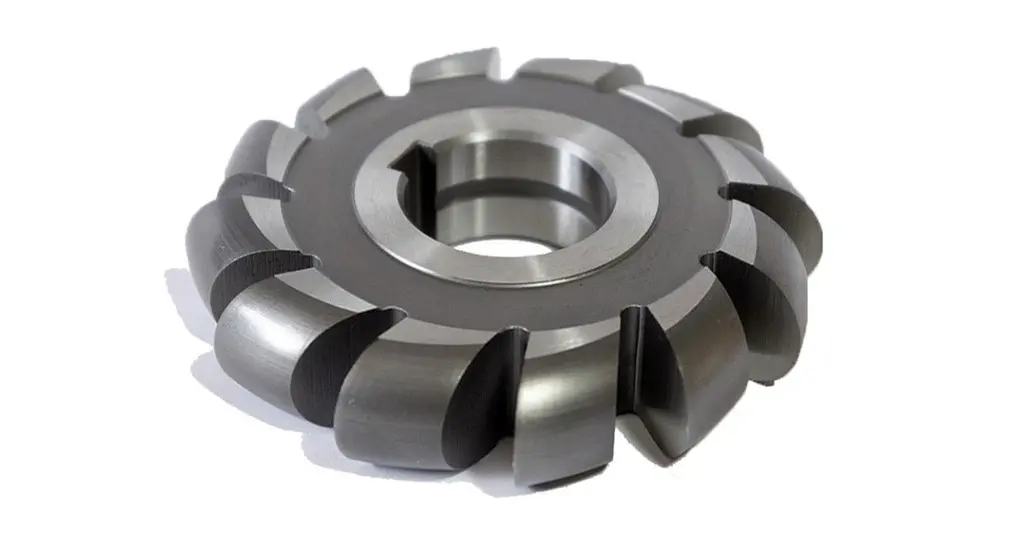
Machining with a gear milling cutter is more efficient than milling with a finger end milling tool. Gear milling cutters are divided into sets corresponding to a specific number of teeth. Due to the varying curvature of the tooth flanks as the number of teeth in the workpiece increases, a different disk cutter should be used for 30 teeth and another for 130 teeth. The tools are normally cataloged according to their various scopes, divided into the so-called sets. Machining, like the end mill, is also performed tooth by tooth until the full profile is obtained.

Fig. 2. Gear Milling cutter [1]
Figure 3 shows a comparison of the kinematics of both forming methods. Point a) shows milling with a gear milling cutter, and in point b) with an end milling cutter.

Fig. 3 Comparison of the work kinematics: a) disk milling cutter, b) end milling cutter [2]
Sources::
-
Ochęduszko K., Koła zębate, tom 2 wykonanie i montaż, Wyd. VI (reprint), 3 dodruk, WNT, Warszawa, 2015, ISBN 978-83063623-05-0
- Dul-Korzyńska B.:, Obróbka skrawaniem i narzędzia, Oficyna Wydawnicza Politechniki Rzeszowskiej, Rzeszów, 2005, ISBN 83-7199-366-8
